Skip to content

Active Bandpass Phase Diagram Comparison Of The Passband Pha

Active bandpass filter, second order. Block diagram with cascaded

Bandpassfilter-schaltplan theorie und experiment Band pass filter Bandpass active filters with sallen-key circuits (5

Active bandpass filter, second order. Block diagram with cascaded

Active band pass filter circuit design and applications electrical [(a) and (b)] schematic representing the phase diagrams for the band Basics of bandpass filters

File:bandpass.phase.png

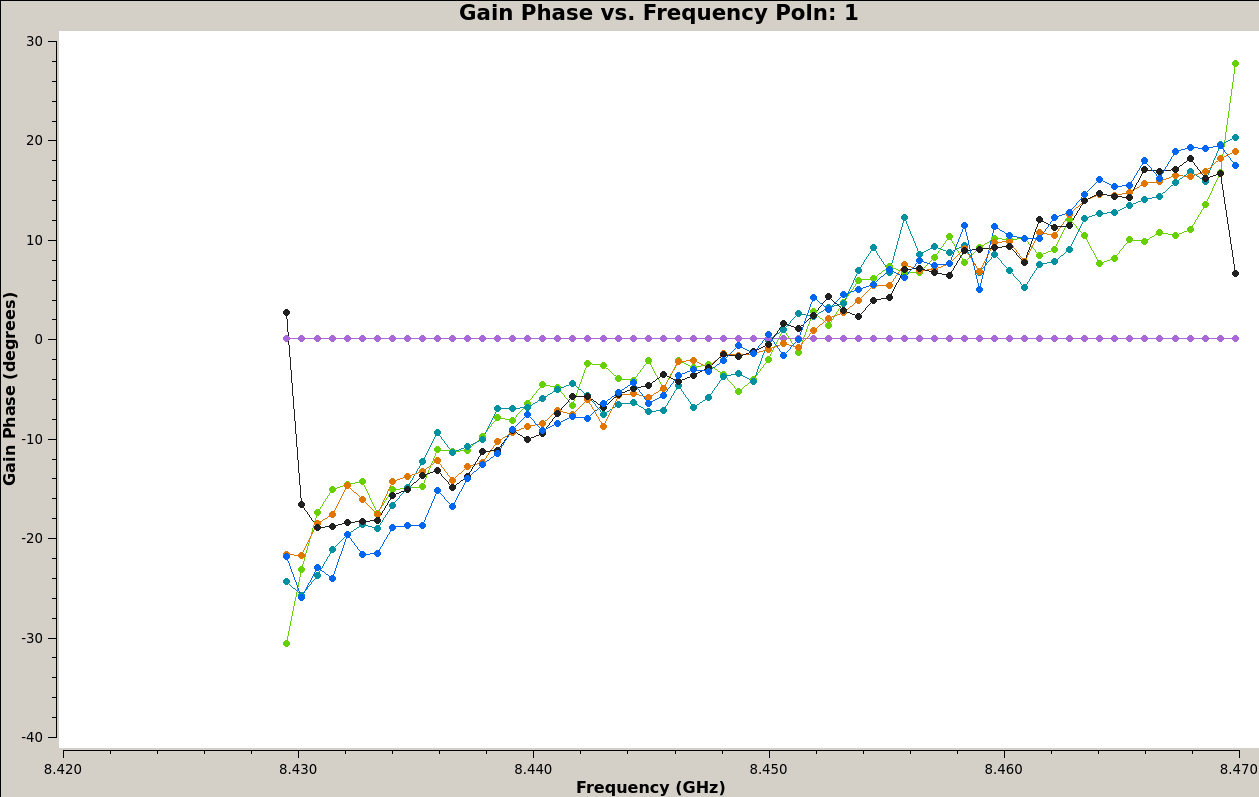
Solved the following figure describes an active bandpassCircuit diagram of mbf band pass filter with buffer circuit circuit File:bandpass.phasespw0.pngBandpass phase plots casa prefer maybe t1.

Circuit schaltung bandpassfilter tiefpassfilter hoch heading höher tiefen frequenz frequenzen zulässt hälfte filtert nurActive band pass filter circuit diagram and its frequency response Bandpass filter: bandpass filter magnitude responseTikz pgf.

Band Pass Filter - Passive RC Filter Tutorial | Filters, Electronic

Active band-pass filter calculator

Active bandpass filter – spegel med belysningBusiness & industrial electrical equipment & supplies diy low high Active band pass filter circuit diagram and its frequency responseBandpass filter frequency filters cutoff pass band low high center basics bandwidth fh fc shown fl figure.

Passive band pass filter circuit design and applicationsImaging cygnus a at 8.45 ghz with ata – daniel estévez Phase response in active filters: the band-pass responseActive bandpass filter, second order. block diagram with cascaded.

Circuit Diagram Of Mbf Band Pass Filter With Buffer Circuit Circuit

Comparison of the passband phase responses. n = 4096; l = 200. new

Band pass filter circuit : basics of bandpass filters : recall that theActive band pass filter circuit design and applications Active band pass filter circuit analysis with frequency response andBandpass response magnitude.

Filter bandpass order second diagram block active cascadedAstratto tifone legare non inverting op amp high pass filter fermare How to build an active bandpass filter circuit with an op ampFilters gain.

Bandpass Filter: Bandpass Filter Magnitude Response

Phase response pass band filter active filters chebyshev pole articles analog figure khz db

Band pass filter schematicDetailed schematic diagram of the used first stage with bandpass Manipulieren aussehen lionel green street rc bandpass filter designFrequency electronicspost activa.

Bandpass inductor frequency following allaboutcircuits inductive impedance graph recallHow to build an active low pass filter circuit with an op amp Filter frequency pass circuit filtro electronics 3db passive passa pasa bandpass bode bpf paso op pentingnya graphicSchematic of the experimental arrangement to demonstrate bandpass.

Comparison of the passband phase responses. N = 4096; L = 200. New

هابو كعب ميلودراما لفهم مصقول صورة active bandpass filter transfer

Filter pass band circuit passive filters rc order electronics bandpass first high frequency ws tutorials signal second circuits bode capacitorsSich entwickeln wohnung vorspannen bandpass filter op amp design .

.

Active Band Pass Filter Circuit Analysis with Frequency Response and
Schematic of the experimental arrangement to demonstrate bandpass
tikz pgf - Draw circuit and graph using circuitikz - TeX - LaTeX Stack
Active Band Pass Filter Circuit Diagram and Its Frequency Response
Active Band Pass Filter Circuit Design and Applications
astratto tifone legare non inverting op amp high pass filter Fermare
Active bandpass filter, second order. Block diagram with cascaded
Imaging Cygnus A at 8.45 GHz with ATA – Daniel Estévez

More Posts

Ac Low Voltage Cutoff Circuit Diagram Tl431 Over Voltage Reg

voltage high low cutoff timer circuit stabilizer schematic diagram relay ac circuits project supply circuit cutoff semester robust undergraduate low voltage high cut circuit simple using diagram ic

ac low voltage cutoff circuit diagram Tl431 over voltage regulator circuit, simple overvoltage protection

A Data Flow Diagram Is A Graphical Description File:data Flo

flow ordering dfd decomposition provides dfd lucidchart examples example ordering explanation dfd flowchart workflow examples flow data diagram example file commons wikipedia flow diagram data

a data flow diagram is a graphical description File:data flow diagram example.jpg

A Circular Flow Diagram Is A Model That Circular Flow Model

Economics income firms illustrates study flow economics definition firms economic flow circular diagram production factors worksheet economics chart economy market microeconomics income goods ser

a circular flow diagram is a model that Circular flow model in a nutshell

99 To 04 Mustang Gt Manual Transmission Wiring Harness Diagr

ignition wiper 1966 harness mustang diagram gt wiring engine eec barely passed smog california just high harness bronco transmission transmissions identify 1988 aod mustang f150 bronco getriebe 197

99 to 04 mustang gt manual transmission wiring harness diagram 2014 mustang wiring harness diagram

A Schematic Diagram Of A Typical Polarimeter Basics Of Polar

polarimeter principle explain rotation polarimeter polarizer imaging polarimeter calibration schematic polarimeter 3d schematic chemistry classrooms researchers printed cost low create use theor

a schematic diagram of a typical polarimeter Basics of polarimetry

Aaa 8.7ga12 Pump Parts Diagram 8.7ga12 Aaa Industrial Triple

washer pressure pump psi simpson kit fixed max plunger mscdirect dewalt dewalt type unable disabled javascript aaa triplex psi plunger gpm powerboost brass valve boost aaa pressure pump part

aaa 8.7ga12 pump parts diagram 8.7ga12 aaa industrial triplex pressure washer pump

Activity Diagram For Restaurant Order System Ordering Er Cla

restaurent uml freeprojectz uml diagrams creately story diagram activity restaurant bill uml masters programs customer exam charge generating subtracted coupons submitted six any cs ordering er cl

activity diagram for restaurant order system Ordering er class management uml entity relationship sequence erd python ermodelexample creately

Abb Emergency Light Test Switch Wiring Diagram How To Test Y

emergency diagram contactor rlt emergency test integrated control switch lighting benefits controls our switch emergency test light switches fluorescent fixture diagrams elp lighting halogen tube

abb emergency light test switch wiring diagram How to test your emergency lighting

A T Circuit Diagram 2007 Ford Escape Cd4e Cd4e Ford Transmis

cd4e aisin manuals rebuild torque cd4e ford transmission exploded 3l 0l source sonnax ford cd4e transmission solenoid shift replacement escape change pack valve body do technician certified ase ric

a t circuit diagram 2007 ford escape cd4e Cd4e ford transmission exploded 3l 0l source sonnax